
Spectrometer interfaces: A guide for OEM instrument designers
Introduction
Spectroscopic instruments are used to analyze the interaction between light and matter in applications ranging from material identification to process monitoring and scientific research. As illustrated in Figure 1, such instruments typically include a light source that illuminates the sample and a spectrometer that detects the
resulting spectrum. An embedded controller coordinates these components, manages timing and data acquisition, and provides the system‑level interface that connects the instrument to a PC, a PLC, or a network.
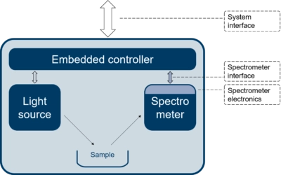
Figure 1: spectroscopic instrument with spectrometer electronics, spectrometer interface and system interface
A central part of this architecture is the spectrometer electronics, which forms the bridge between the optical detector inside the spectrometer and the instrument’s embedded controller. The electronics converts the analogue video signal from the detector into a digital data stream and generates the timing, synchronization, and control signals required for stable and repeatable spectroscopic measurements.
The interface to the spectrometer generally needs to transfer far more data than the system‑level interface. The spectrometer interface must read out raw data from all detector pixels, whereas the system interface often provides higher‑level, compressed information such as concentration values, material identification, or simple pass/fail results.
Instrument builders can choose from several interface technologies for connecting the spectrometer electronics to the embedded controller — ranging from low‑level embedded interfaces such as SPI and MIPI to higher‑level PC‑oriented interfaces like USB and network‑oriented interfaces such as Ethernet. Selecting the right interface is not trivial: it directly influences timing accuracy, achievable frame rate, system architecture, robustness, and long‑term maintainability.
This white paper helps OEM integrators answer a practical and often decisive question: which electronics interface is best suited for my spectrometer‑based instrument — both during early development and in the final embedded design?
Download the full white paper:
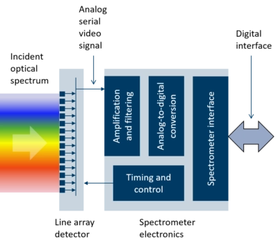
Figure 2: Overview of key functions in spectrometer electronics
Overview of spectrometer electronics
A spectrometer consists of a linear array detector that converts light intensity into electronic charge in each pixel. Unlike image sensors used in consumer and industrial cameras, most linear array detectors for spectroscopy do not integrate an on-chip analog-to-digital (A/D) converter. Instead, they output an analog video signal that must be digitized by external electronics. This analog interface is inherently sensitive to noise pickup and external interference, making careful electronics design essential for achieving high SNR.
As shown in Figure 2, the signal from the detector passes through low noise amplification and filtering stages before being digitized by an A/D converter. Timing control — including integration start/stop, readout clocks, and other control signals — is typically handled by a Field-Progammable Gate Array (FPGA) or microcontroller. The resulting digital data must then be formatted and transmitted through the spectrometer interface for further processing in the instrument’s embedded controller.
Typical use cases
The choice of the most suitable spectrometer interface depends strongly on how the spectrometer will be used. In practice, the interface requirements fall into one of three typical use‑case categories.
OEM instrument integration
When integrated into an instrument, the spectrometer connects directly to a microprocessor over a short distance. Deterministic timing, low latency, and minimal protocol overhead are essential. Interfaces such as SPI and MIPI are well suited for this environment because they integrate naturally with microcontrollers and provide precise control over timing and synchronization.
Early stage evaluation and trouble shooting
Instrument development often begins on a laptop or PC. USB and Ethernet are ideal here because they are plug and play, require no custom hardware, and are supported by high level programming environments such as Python, MATLAB, and LabVIEW.
Spectrometer as stand-alone instrument
In some applications, the OEM spectrometer is not embedded inside a larger instrument but is instead used directly by the end user as a standalone measurement device. This is common in research laboratories, scientific experiments, prototyping environments, and small‑scale industrial setups. In these situations, the spectrometer’s own interface effectively becomes the system interface, and ease of connection to a PC or network becomes a priority making USB and Ethernet attractive.
However, industrial end‑user environments follow a very different pattern. Standard USB is rarely used due to robustness, EMI, and connector‑lifetime concerns. And while Ethernet is common in automation systems, it is typically not the standard Ethernet found on consumer devices. Instead, industrial networks rely on specialized variants such as EtherCAT, PROFINET, Ethernet/IP, Time‑Sensitive Networking (TSN), none of which are normally supported by OEM spectrometers. As a result, even when the spectrometer is used directly in an industrial setting, the interface requirements often exceed what typical USB/Ethernet‑based spectrometers can provide.
Considerations when selecting an interface
The choice of interface depends on how the spectrometer will be used and which performance parameters matter most for the application. Several fundamental characteristics influence whether an interface is suitable for a given design.
Frame rate
The maximum supported bit rate is a fundamental parameter of any interface. For spectrometers, it is determined by the number of pixels, the bit depth used to represent the signal level on each pixel, and the required frame rate – that is, the number of spectra that must be read out every second. The required interface bit rate therefore scales directly as:
Interface bit rate=(Number of pixels) x (Bit depth) x (Frame rate)
For example – a detector with 2048 pixels digitized with a 16 bits A/D converter would demand an interface bit rate of at least 328 kbit/s if only 10 spectra per second (10 Hz frame rate) is needed but more than 32.8 Mbit/s if 1000 spectra should be read out every second (1 kHz frame rate).
Synchronization, latency, and responsiveness
Many spectroscopy applications depend on precise control of exposure timing, triggering, and coordination with external equipment such as pulsed lasers or shutters. The interface plays a central role in determining how accurately these timing events can be generated and how quickly the system can react to commands. Some interfaces provide tightly controlled, deterministic timing with minimal jitter and near‑instantaneous command execution, while others introduce variable latency due to buffering or host‑side scheduling.
These differences become critical in applications that rely on microsecond‑level synchronization, rapid adjustments of integration time, or closed‑loop operation where timing precision directly affects measurement performance.
Cable length and noise immunity
Different interfaces support different cable lengths and connector types, which can influence mechanical design and system layout. Short‑range interfaces are well suited for compact embedded systems where the spectrometer sits close to the controller. Longer‑reach interfaces become important when the spectrometer must be located far from the processing electronics. The choice of interface also plays a decisive role for noise immunity. Interfaces that use digital differential signaling reject common‑mode noise and tolerate longer cables. Good grounding practices and shielded cabling also helps.
Software development eco-system
The software environment surrounding an interface is just as important as its electrical characteristics. Reliable drivers, stable APIs, and well‑maintained SDKs determine how easily the spectrometer can be integrated into an application and how quickly developers can begin acquiring data. Interfaces supported by mature software stacks allow seamless access from high‑level environments such as Python, MATLAB, and LabVIEW, while also providing low‑level control for embedded systems. A robust software eco‑system reduces development time, simplifies long‑term maintenance, and ensures that the spectrometer can be integrated consistently across different platforms and operating systems.
Long‑term availability
Spectrometer‑based instruments often remain in production for decades, which makes the long‑term stability of the chosen interface an important design factor. Interfaces that follow well‑established standards tend to offer predictable evolution and backward compatibility, reducing the risk of forced redesigns as new generations appear. In other cases, very simple interfaces with minimal protocol complexity remain unchanged for decades and provide a reliable foundation for long‑lived products.
Hardware requirements and interface complexity
Different interfaces place very different demands on the surrounding electronics, and this can strongly influence both cost and system architecture. Simple interfaces such as SPI can often be connected directly to a microcontroller with minimal external components, making them attractive for compact embedded systems. More advanced interfaces such as USB or Camera Link, however, may require dedicated hardware such as PHY chips or external frame‑grabber cards. These components add complexity, increase power consumption, and cost.