
Pulse front tilt calculator
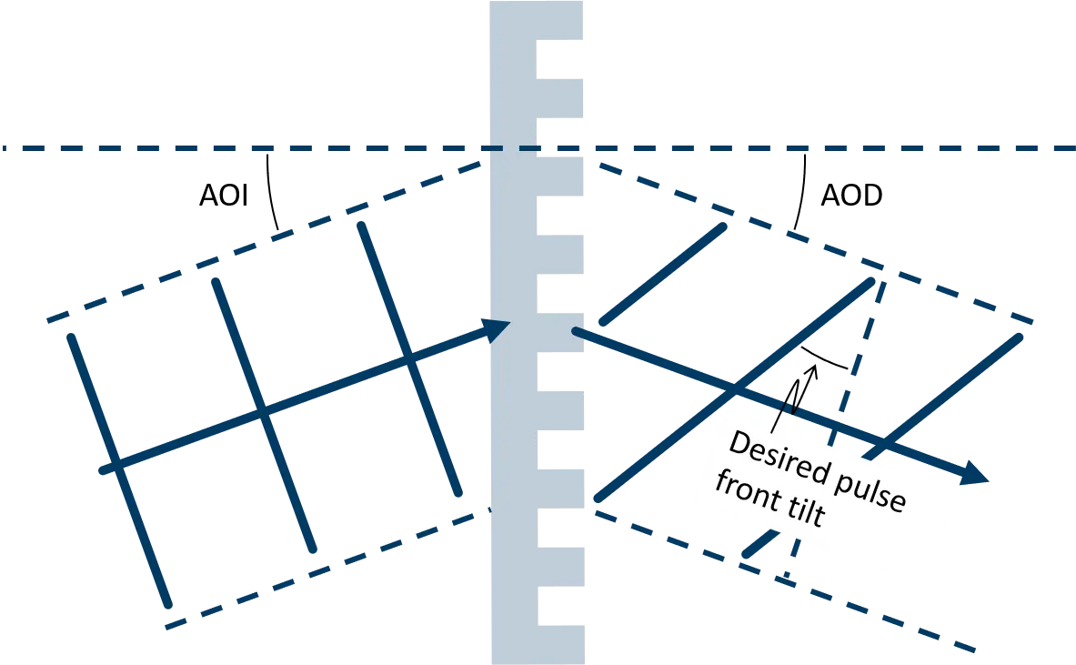
Pulse-front tilt is a critical parameter in ultrafast laser systems and THz generation setups, where precise matching of optical propagation conditions is required. In grating-based pulse-front tilt schemes, the tilt is determined by the grating geometry and diffraction conditions, which define the relationship between wavelength, groove density, angle of incidence (AOI), and angle of diffraction (AOD).
This calculator determines the AOI and AOD required to achieve a specified pulse-front tilt for a given wavelength and transmission grating groove density. By linking the desired pulse-front tilt directly to the grating configuration, the tool helps researchers and engineers quickly identify suitable operating conditions and optimize system performance.
Fused-silica transmission gratings are particularly well suited for pulse-front tilt generation because they provide high diffraction efficiency, stable angular dispersion, and excellent laser damage resistance. These properties enable precise, repeatable control of pulse-front tilt in demanding scientific and industrial applications, including high-efficiency THz generation.
Pulse front tilt calculator |
The plot below shows the calculated AOI and AOD for the required pulse front tilt as a function of grating resolutions.
Pulse front tilt theory
When an ultrashort pulse is diffracted by a grating, different wavelength components propagate at slightly different angles due to angular dispersion. This causes the pulse front, which represents the surface of constant arrival time within the pulse, to become tilted relative to the beam propagation direction.
The pulse-front tilt angle is determined by the diffraction geometry and can be related to the grating period, wavelength, and diffraction angle. For a transmission grating operating in diffraction order m, the diffraction angle is governed by the grating equation
| mλG = sin(AOI) + sin(AOD) |
where G is the grating resolution, λ is the wavelength, AOI is the angle of incidence, and AOD is the angle of diffraction.
The resulting pulse-front tilt angle γ is given by
| tan(γ) = | mλG |
| cos(AOD) |
showing that the tilt depends on both the grating resolution and the diffraction geometry. For a specified wavelength, resolution, and desired pulse-front tilt, these relationships can be used to determine the AOI and AOD required to achieve the target operating condition.
Calculation of of AOI and AOD for a desired pulse front tilt angle
For a specified wavelength, grating groove density, and desired pulse-front tilt, the diffraction angle (AOD) is first determined from the pulse-front tilt equation:
| AOD = cos-1( | mλG | ) |
| tan(γ) |
where G is the grating resolution, m is the diffraction order, and γ is the desired pulse-front tilt.
The angle of incidence (AOI) is then obtained from the grating equation:
| AOI = sin-1(mλG – sin(AOD)) |
The calculator uses these relationships to determine the AOI and AOD required to generate the specified pulse-front tilt for the selected wavelength and grating resolution.
Want to know more?
For further information see below.