How to build a fluorometer
A fluorometer, also known as a spectrofluorometer, is an instrument that is capable of measuring the optical fluorescence from one or more fluorophores. On this page, we illustrate the basics of a fluorometer design.
You can learn more about the basics of fluorescence spectroscopy by clicking here or watch our video tutorial here..
There are many types and names for instruments capable of measuring fluorescence, like fluorometer, fluorimeter, fluorescence spectrophotometer, and micro plate reader. You can get a more detailed description here. A fluorometer is generally used to describe an instrument with a dedicated application in mind such as chorophyll measurements.
The function of a fluorometer is to illuminate the sample with light at a specific wavelength and measure the emitted fluorescent light from the sample at one or more wavelengths. The figure below shows the basic construction of a fluorometer.

A fluorometer consists of the following basic components:
Below, the various components are described in more detail.
The light sources commonly used for fluorometers are Light Emitting Diodes (LEDs) due to their compact size, relatively low cost and good conversion efficiency. LEDs are available at many different center wavelengths and typically covers a bandwidth around the center wavelength of 10 – 50 nm. The choice of the LED depends on the excitation wavelength you need for your fluorophore. As an example chlorophyll absorbs light in both the blue (465 nm) and red (665 nm) range. So you may want to use a white LED which covers the full visible spectrum as your excitation source (see an example here. Alternatively you can choose to use only a blue LED (for instance a 465 nm LED like the one here. The LED will in general emit light in a cone around the main direction of light and thus it can often be beneficial to incorporate a collimating lens in front of the LED.
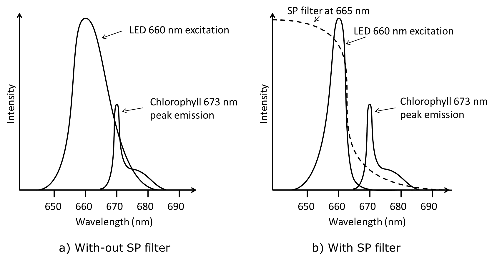
In order to limit the amount of direct light from the LED that ends up on the detector where it can disturb the much weaker fluorescence signal a short pass optical filter is normally used as excitation filter. A good example is Chlorophyll, which has an absorption peak at 665 nm and an emission peak at 673 nm. If we use a LED at 660 nm it will also emit significant amounts of light at in the 670 – 680 nm range so, it can be difficult to separate this light from the fluorescence signal of Chlorophyll as shown on a) figure below. When a short pass filter with the edge at 665 nm is used it becomes much easier to measure the fluorescence as shown on figure b).

The choice of sample holder really depends on the application. The main thing to consider is that in the case a transmissive cuvette or flow cell you must ensure that the sample holder material is transparent for both your excitation and emission wavelength. This is especially important for UV wavelengths where most glasses absorb light so special types of materials needs to be used.
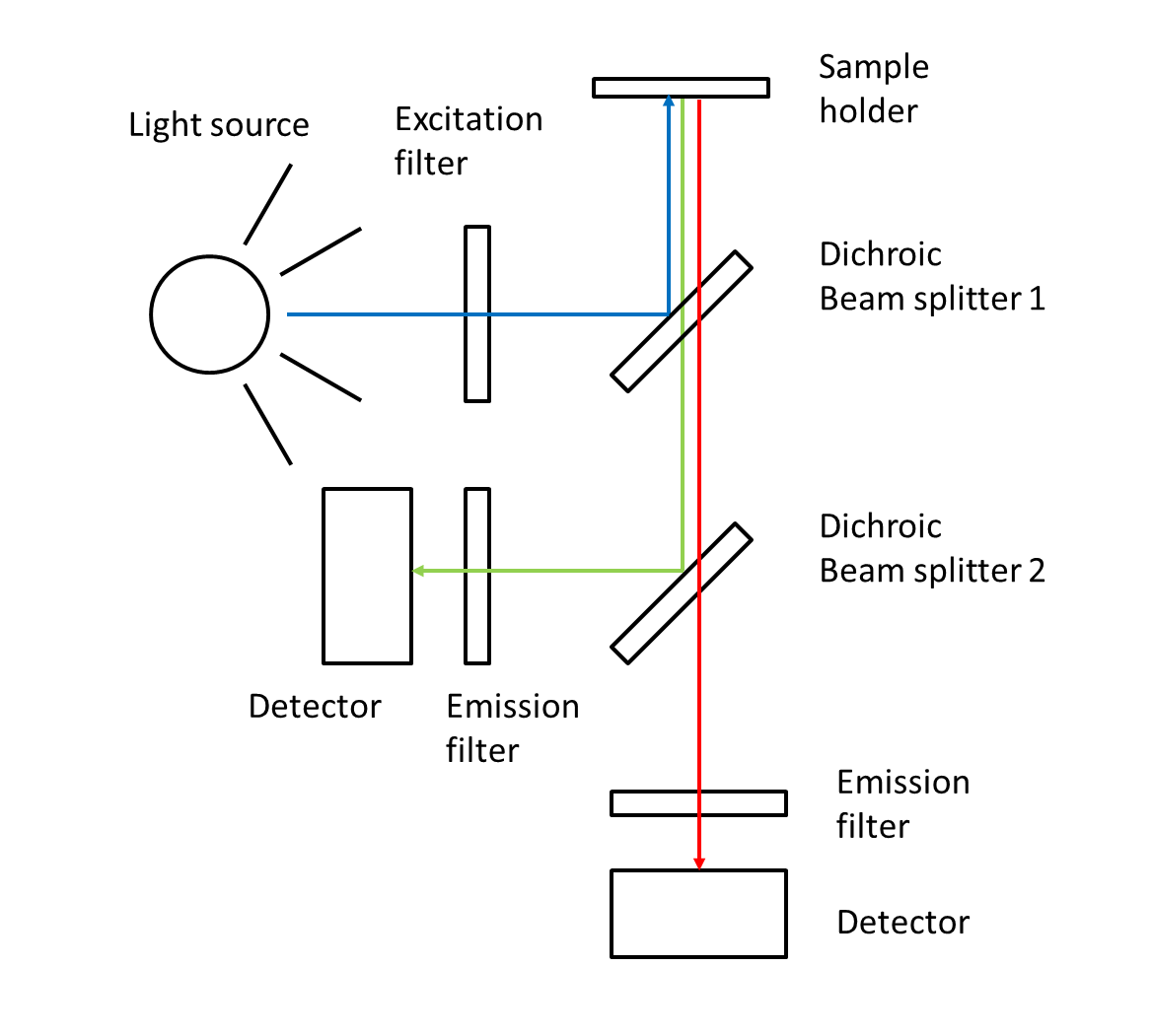
The function of the dichroic beam splitter is to reflect the shorter wavelengths and transmit the longer wavelengths. In this way the excitation light from the LED gets directed to the sample whereas the collected fluorescent emission is directed to the detector. An example of a dichroic beamsplitter for 650 nm can be seen here.
In some cases where multiple emission wavelengths are to be measured simultaneously, more than one dichroic beam splitter might be used as shown in the picture below.

The final part of the fluorometer is the detector. The detector converts light (photons) into an electronic signal in the form of electronic charge, current or voltage. It is common to use single Photo-Multiplier Tubes or Silicon photodetectors. However, if you need to analyze multiple fluorophores and peaks it may be more beneficial to use a diode array spectrometer like our PEBBLE VIS. Such a device will record the full spectrum of all peaks sampled at several hundred wavelengths. A design example is shown on the figure below.

Measuring Fluid Fluorophores with our PEBBLE Spectrometer
Want to know more?
For further information see below.