Pulse front tilting
Application Note
By Dines Nøddegaard Erschens, Grating Engineer and Kristian Buchwald, VP Gratings. Published November 13th, 2019.
The application note is located at the bottom of this page in downloadable .pdf format. Should you have difficulty downloading, feel free to contact us using the dialogue options at the top right of this page, we will be happy to e-mail you a copy.
Introduction
Pulse front tilt is a term that describes the phenomenon of an ultrashort pulse having a pulse front that is tilted relative to the propagation direction of the beam. Tilted pulse fronts have a notable application being phase-matched Terahertz (THz) generation by optical rectification of femtosecond laser pulses in LiNbO3. Diffraction gratings – and especially transmission gratings – provide an efficient method to generate the required pulse front tilt.
This technical note aims to explain the concept of optical rectification, the requirement for pulse front tilting, and derive practical equations to calculate the pulse front tilt of a grating configuration.
Optical rectification explained
Optical Rectification is a non-linear process that can be used to generate a single cycle terahertz signal.
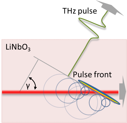
When the generating pulse propagates through the non-linear crystal it will at each point in time induce a polarization density in the crystal, the DC (zero frequency) terms of which will follow the envelope of the pulse and will in turn generate a single cycle electromagnetic signal. For ultrashort pulses of 100ps or below, this signal can contain frequencies in the THz range. Each generation point will act as a point source with the THz signal propagating in all directions. The macroscopic THz-signal will propagate in the directions where the generated signals sum up in phase (Huygens’ Principle).
Efficient generation of THz radiation requires the signals generated at different points in time to be phase matched and thus interfere constructively.
If the group velocity of the generating pulse and the propagation velocity of the generated THz-signals match, the pulse will follow the forward propagating signal and the signals generated in all points in time will sum up in phase in the forward direction. This is called collinear velocity matching and it is possible for e.g. optical rectification of 800nm laser pulses in Zinc Telluride (ZnTe).

Requirement for pulse front tilting
In general, however, the group and propagation velocities do not match, i.e. the THz signals generated at different points along the propagation sum up in phase at an angle to the propagation direction. As the pulse has a non-negligible spot size, THz-signals generated at different point on the spot will have the same propagation direction but generally not sum up in phase.

If the pulse front is however tilted at the right angle (matching the angle of the phase front of the generated THz-signal), it is possible to have the contributions from all parts of the spot add up in phase.
The required pulse front angle is calculated from the group velocity of the generating pulse (νgr) and the (phase) velocity of the generated THz-signal (νsignal).
| γ = cos-1 ( | νsignal | ) = cos-1 ( | nsignal | ) |
| νgr | ngr |
Where the group velocity of the generating pulse is given by:
| γgr = | c |
| ngr |
and the group refractive index in the crystal of the generating pulse (which is temporally short and spectrally broad) is:
| ngr = nλ0 – λ0 | dn |
| dλ0 |
Where λ0 is central wavelength of the pulse in vacuum and n is the (phase) refractive index of the crystal.
Generation of pulse front tilt using transmission gratings
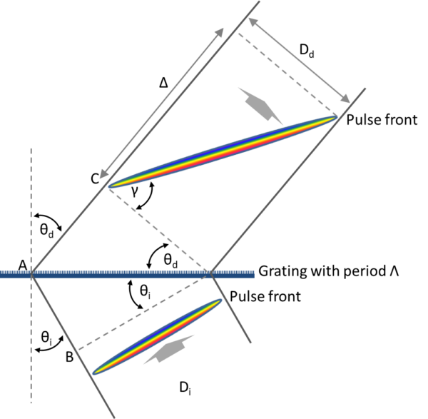
As depicted in the drawing below, the left and right side of a laser pulse diffracted by a transmission grating at an angle { \theta }_{ d } will have a path length difference of Δ, resulting in a tilt of the pulse front (constant amplitude) of γ .

Assuming a straight pulse front in the incident pulse and equal path length for left and right side of the pulse front going through the grating, the pulse front tilt angle (γ) can be derived from the above figure.
The path difference (Δ) consists of the contributions before (|AB|) and after (|AC|) diffraction, which can be written in terms of incident and diffracted beam widths Di and Dd and angles θi and θd.
| Δ = |AB| + |AC| = | Ditan(θi) + Ddtan(θd) = | Di | sin(θi) + | Dd | sin(θd) |
| cos(θi) | cos(θd) |
As the incident and diffracted pulse have the same width in the grating plane:
| Di | = | Dd | ⇒ Δ = | Dd | (sin(θi) + sin(θd)) |
| cos(θi) | cos(θd) | cos(θd) |
And γ can be found as:
| tan(γ) = | Δ | ⇒ γ = tan-1( | sin(θi) + sin(θd) | ) |
| Dd | cos(θd) |
Substituting the sines with the grating equation mλ = Λ(sin(θi) + sin(θd)), where m is diffraction order, λ is wavelength and Λ is the grating period, this gives:
| γ = tan-1( λ | m | ) |
| Λ cos(θd) |
If after diffraction the pulse passes through an imaging system having a magnification of βm (giving a pulse width of D= βmDd) and enters a medium with group refractive index ngr (giving λ= λ0/ngr, where λ0 is the wavelength in vacuum) the pulse front tilt changes to:
| γ = tan-1( | λ0 | m | ) | |
| ngr | βmΛ cos(θd) |
The pulse front tilt can also be related to the angular dispersion by isolating the diffraction angle in the grating equation and differentiating with respect to wavelength, giving:
| dθd | = | m |
| dλ | Λ cos(θd) |
Thus the pulse front tilt angle resulting from diffraction by a transmission grating is related to the angular dispersion (dθd/dλ) of that grating:
| γ = tan-1( λ | dθd | ) |
| dλ |
Want to know more?
For further information see below.